
Search News
Industry Portal
Hot Articles
How fatigue affects the choice of industrial product materials
Time
Click Count
Select industrial product materials for the stress cycles a finished component will experience, not solely for the highest load it can carry once. A higher-strength alloy can reduce section size, yet a rough thread root, a corrosive environment, or an unfavorable heat treatment can erase its apparent fatigue advantage. The useful comparison is between manufactured components under the same loading, surface, and environmental conditions.
Begin with the expected load history and the location where cracking would be most consequential. Then compare candidate materials using fatigue data that reflects the intended geometry and process. For a bolt, this includes preload and thread condition; for a tool shaft, bending and torsion; for a protective component, repeated flexing and environmental exposure. Static strength remains necessary to prevent yielding or fracture under peak load, but it does not establish service life under repeated loading.
Turn service loads into a fatigue comparison
Fatigue damage accumulates under fluctuating stress. A component can crack even when each individual load is below its yield strength. The relevant stress is often local: a shoulder, hole, groove, thread root, or weld transition can experience a higher stress than the nominal value calculated across the section.
Describe the load cycle by its maximum and minimum stresses, stress range, and mean stress. Alternating stress is half the range; mean stress is the average of the maximum and minimum. Two components with the same stress range can have different fatigue lives if one cycle has a larger tensile mean stress. For example, a rotating shaft under bending experiences alternating tension and compression at a surface point, while a preloaded fastener generally remains in tension as its load fluctuates.
Cycle count matters as much as load magnitude. A motor shaft can accumulate many cycles during ordinary operation, whereas a structural connection may experience fewer but more severe load reversals. A spectrum containing frequent small cycles and occasional large ones is better represented by a load history than by a single average load. Starting, stopping, jamming, vibration, and handling can all introduce cycles that a steady-state calculation misses.
When measured loads are unavailable, define plausible operating cases and identify which assumptions control the result. A material comparison based on an optimistic duty cycle is weak even if both candidates are evaluated with the same calculation.
Read fatigue data alongside its test conditions
An S–N curve relates cyclic stress to the number of cycles to failure under specified test conditions. It is useful for comparing materials, provided the curves use compatible stress definitions, load ratios, surface finishes, specimen sizes, temperatures, and failure criteria. A polished laboratory specimen under fully reversed loading does not directly represent a threaded fastener in a damp assembly.
Fatigue results also scatter. An isolated data point is a poor basis for a durability claim; a design curve should account for the required reliability and the variability represented in the underlying tests. When data is limited, compare the consequences of failure and the sensitivity of the design to changes in fatigue strength. A small calculated advantage may disappear within test scatter or manufacturing variation.
Some steels exhibit a fatigue limit under particular laboratory conditions, while many aluminum alloys are assessed at a specified number of cycles rather than assigned a universal endurance limit. Corrosion, variable-amplitude loading, elevated temperature, and other service conditions can invalidate a simple constant-amplitude interpretation. State the cycle count and test environment whenever quoting a fatigue strength.
High-cycle fatigue is often evaluated using stress-based methods when cyclic deformation is predominantly elastic. Under repeated local yielding, such as severe startup loads or assembly deformation, strain-based low-cycle fatigue analysis is more appropriate. If a crack-like defect is already present or must be tolerated, fracture mechanics can help assess crack growth and inspection intervals. These approaches answer different questions; selecting one requires knowing whether the concern is crack initiation, propagation, or both.
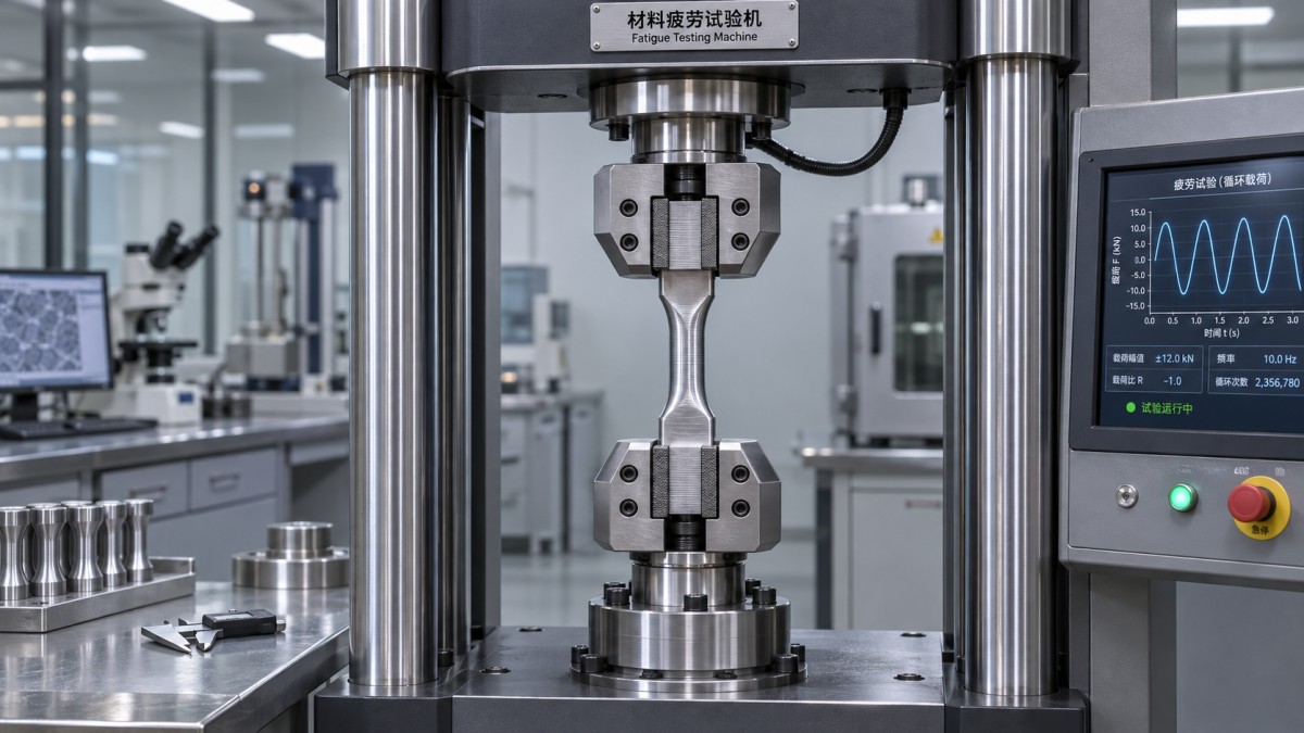
Material strength changes the trade-offs
Higher tensile strength often improves fatigue resistance in smooth, controlled specimens, but that relationship becomes less reliable at notches and damaged surfaces. Higher-strength steels can be more sensitive to surface defects and, under susceptible material and environmental conditions, hydrogen-related cracking. A strength upgrade therefore deserves a review of plating, cleaning, residual stress, and inspection as well as the static load calculation.
Aluminum alloys offer low density and can suit moving assemblies where mass matters. Their lower elastic modulus means an aluminum part of the same geometry deflects more than a steel part under the same load. Increasing section dimensions can restore stiffness and reduce stress, but the resulting shape and joints must fit the available space. Compare fatigue performance at the intended life and environment rather than assuming that a lightweight substitution preserves the original design margin.
Stainless steels can reduce some corrosion concerns, but corrosion resistance and fatigue strength vary with grade, surface condition, and environment. A stainless substitution is not automatically immune to pitting or corrosion fatigue. Titanium alloys provide high strength relative to density, yet their finished-part performance still depends on surface integrity, contact conditions, and the chosen alloy and heat treatment.
Polymers and fiber-reinforced composites require a different comparison. Repeated loading can produce matrix cracking, fiber damage, delamination, creep, or progressive loss of stiffness. Temperature, moisture, load frequency, and fiber orientation can change the result. A published tensile strength measured in one direction is insufficient for a protective shell or housing exposed to repeated bending and impact; test the relevant laminate or molded part in its intended orientation.
The manufacturing route is part of the material specification
Cracks commonly initiate at surfaces, so the same alloy can deliver different fatigue performance after different processes. Machining marks that run across the principal tensile stress, sharp tool marks, grinding damage, pits, and burrs can all create initiation sites. A generous transition radius and an appropriate surface finish often improve fatigue performance without changing the alloy.
Residual stresses also affect the local cycle. Controlled shot peening or suitable rolling processes can introduce compressive stress near the surface, delaying crack initiation under tensile cycling. The benefit depends on coverage, process control, geometry, and whether subsequent heating or service exposure relaxes that stress. Excessive or poorly controlled treatment can damage the surface. Specify the process and verify the resulting condition rather than treating a treatment name as a guaranteed improvement.
Welded assemblies need particular attention because the weld toe, root, defects, distortion, and tensile residual stresses can dominate fatigue behavior. Increasing the base metal strength alone may offer little improvement if the critical crack starts at an unchanged weld detail. Joint geometry, weld quality, loading direction, and any qualified post-weld treatment belong in the comparison. Welded-detail fatigue data should be applied only within the conditions for which it was developed.
For additive manufacturing or cast parts, internal porosity and surface condition deserve explicit consideration. Defects close to a highly stressed surface can shorten life; their significance depends on size, location, shape, and loading. Inspection methods have detection limits, so acceptance criteria should relate detectable indications to the part’s stress field and required life.
Fasteners: evaluate the joint, not the bolt alone
In a properly designed preloaded joint, clamped members and the bolt share changes in external load. Joint stiffness and preload influence how much of that change reaches the bolt. If separation or slipping occurs, the load path can change and the bolt can experience a larger cyclic load or bending. A higher-strength bolt does not compensate for an unsuitable joint design or inconsistent installation.
The thread root is a common fatigue-critical location. Thread geometry, surface condition, and the relationship between thread rolling and heat treatment can affect residual stress and fatigue performance. Compare fasteners in the finished condition, including coatings and any subsequent processing. Plating and cleaning routes for susceptible high-strength steels also require control of hydrogen exposure and appropriate verification.
Installation details belong in the fatigue assessment: preload method, lubrication, bearing surfaces, alignment, grip length, and the stiffness of the clamped parts all affect joint behavior. Torque alone is an indirect measure of preload because friction varies. If the load is critical, the chosen preload verification method and its uncertainty should be reflected in the design margin.
Match the environment to the failure mechanism
Corrosion pits can become crack initiation sites, and cyclic stress can accelerate damage in a corrosive environment. A fatigue curve measured in dry air may therefore overstate the life of a component exposed to water, salt, chemicals, or trapped condensation. Protective coatings and seals can reduce exposure, but coating damage, crevices, and maintenance intervals must be considered in the service scenario.
Contact between parts introduces a different problem: fretting. Small repeated slips at a joint or bearing surface can damage the surface and create sites for fatigue cracks. Increasing material strength without controlling contact pressure, slip, surface condition, or fit may leave the dominant mechanism unchanged.
Temperature changes can affect strength, stiffness, residual stress, and environmental attack. Repeated thermal expansion can itself generate cyclic stress where dissimilar materials are constrained together. For a metal insert in a polymer housing, for example, both the temperature range and the restraint at the interface matter when assessing repeated thermal cycles.
Use finished-part evidence to resolve close choices
When candidate materials look similar on paper, test representative components rather than relying on a single coupon value. Include the intended heat treatment, surface finish, coatings, joints, and assembly method. Apply a load spectrum that represents service, with special attention to the highest-stress features. Record where cracks start as well as when failure occurs: an unexpected initiation site may point to a manufacturing or assembly issue that a material substitution will not solve.
Define the acceptance basis before testing: required load history, environment, number of specimens, failure definition, and the treatment of runouts—specimens that reach the test limit without failure. A runout establishes survival to that point under those conditions; it does not establish unlimited life. If inspection is part of the service strategy, connect the inspection method and interval to detectable crack size and expected growth, rather than assuming that a visible crack will provide sufficient warning.
The final material specification should identify the condition being purchased and evaluated: grade, heat treatment, relevant surface and process requirements, and the fatigue evidence used for the critical feature. That detail makes later substitutions reviewable when a different process, coating, or supplier changes the surface or defect population that controls life.
Recommended News