
Search News
Industry Portal
Hot Articles
How to select aerospace titanium solid rivets for joint thickness
Time
Click Count
Selecting aerospace titanium solid rivets for the correct joint thickness involves more than matching a fastener to the material stack. Rivet length must accommodate the measured grip and provide sufficient material to form a compliant shop head, while diameter, head style, material specification, and installation method must meet the applicable engineering requirements.
This guide helps technical evaluators assess grip range, account for manufacturing tolerances, and verify selections against approved drawings and fastener standards before installation.
Start with the actual joint thickness, not the nominal stack
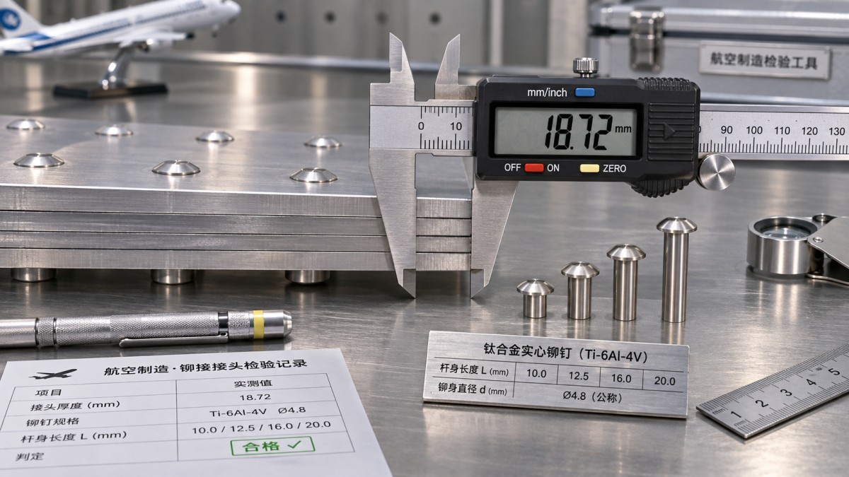
Joint thickness, often called grip, is the total thickness of the materials clamped by the rivet. Measure the complete stack at the intended fastener location.
Include every layer the approved design requires, such as shims, doublers, and permanent interlayers. Account for coatings or sealant where the governing installation instructions specify their inclusion.
Use the drawing to establish the permitted grip range, then check production measurements against it. A nominal dimension alone does not capture variation across an assembly.
For an existing assembly, measure accessible layers with calibrated instruments before joining. Where direct measurement is impractical, use an approved method for establishing the assembled stack.
Check for local gaps, burrs, deformation, and trapped debris. A calculated grip can look acceptable while an unseated stack produces a loose or nonconforming joint.
The selection must cover the thinnest and thickest permitted stacks, subject to the fastener specification. Different stack combinations may require different rivet lengths or an approved engineering disposition.
How much rivet length is needed for a given grip?
As a selection framework, start with measured grip and add the protruding shank length required to form the shop head. Then select an available length permitted by the specification.
The shop head is the head formed during installation, opposite the manufactured head. Its final dimensions and shape must satisfy the applicable installation and inspection requirements.
A common preliminary estimating convention for some solid rivets uses protrusion of about 1.5 times the nominal rivet diameter. Treat this only as an initial estimate.
Titanium alloy, head configuration, tooling, forming process, and the governing specification can require different values. Do not use a general rule to override approved aerospace installation data.
For illustration, suppose a 0.125-inch-diameter rivet joins a measured 0.250-inch stack. An estimating allowance of 1.5 diameters gives approximately 0.188 inch of protrusion.
Adding those values yields an estimated rivet length of 0.438 inch. This is a calculation example, not an approved part selection or a universal titanium installation requirement.
Before ordering, confirm how the relevant part standard defines and measures length. Countersunk and protruding head configurations can use different length references, changing the required designation.
Next, check available length increments and verify that the selected part produces acceptable protrusion and shop heads across the allowed grip range. Do not assume rounding upward is always acceptable.
Too little material can produce an undersized shop head. Excessive protrusion can make forming difficult or contribute to bending and an unacceptable head, depending on the process.
How should tolerances affect rivet selection?
Build a stack-up using the minimum and maximum permitted thicknesses of all relevant layers. Include measurement uncertainty and process allowances where required by the engineering documentation.
For example, three nominal 0.080-inch layers give a nominal grip of 0.240 inch. If each independently varies by plus or minus 0.005 inch, the arithmetic extremes are 0.225 and 0.255 inch.
That example assumes all three layers can simultaneously reach their respective limits. Use the tolerance method required by the design; statistical assumptions need an engineering basis.
Evaluate minimum grip against the maximum permitted protrusion and maximum grip against the minimum permitted protrusion, using the applicable fastener and installation tolerances.
Also consider rivet length variation, hole preparation, surface condition, and any approved countersink or dimple geometry. Each can affect the installed configuration or inspection result.
If one length cannot meet requirements at both extremes, do not compensate by improvising during installation. Review available lengths, stack controls, or an engineered change with the responsible authority.
Document the assumptions and limits used in the evaluation. This makes the choice repeatable when suppliers, material lots, or manufacturing conditions change.
Does joint thickness determine rivet diameter?
Grip helps determine length, but it does not independently establish diameter. Diameter and spacing are normally specified by the joint design or an approved repair scheme.
The engineering assessment may address applied loads, fastener shear, sheet bearing, edge distance, spacing, fatigue, and the properties of the joined materials.
Hole diameter and fit also matter. A rivet that matches the stack thickness can still be unsuitable if it does not meet the specified hole and fit requirements.
Do not substitute a larger diameter merely to address a long grip or a damaged hole. An oversize fastener can change edge distance, bearing behavior, and fatigue performance.
For repairs, follow the applicable structural repair manual or approved engineering instruction. Unspecified hole enlargement or fastener substitution requires the appropriate engineering approval.
Which head style and length measurement apply?
Protruding heads and flush heads serve different joint geometries. The drawing should identify the required configuration, including whether a countersink or dimple is permitted.
A flush installation depends on the specified head angle, hole preparation, and seating. Incorrect geometry can leave the head proud, too deep, or inadequately supported.
When interpreting a part number, use its exact fastener standard to determine how head style and length are encoded. Similar-looking designations are not necessarily interchangeable.
Confirm where the standard starts and ends its length measurement. Compare that definition with the grip calculation before deciding which catalog length meets the design.
Also check access on the shop-head side. Restricted clearance may affect the ability to position a bucking bar or other approved forming equipment.
What titanium specification and installation method are required?
“Titanium” alone is not a complete material requirement. Confirm the specified alloy, condition, fastener standard, finish if applicable, and any product qualification or procurement requirements.
Mechanical properties and formability depend on the specified material and processing. A rivet with the right dimensions is not acceptable if its material or condition differs from the drawing.
Review the approved installation process before purchasing. Titanium fasteners may require particular equipment, forming procedures, or controlled conditions described in the applicable technical data.
Check that the production team can access both sides, control the forming operation, and inspect the finished head. A geometrically suitable part may be impractical in a constrained joint.
Do not assume that procedures used for aluminum solid rivets transfer directly to titanium. Use the specified tooling, process parameters, and acceptance criteria for the actual fastener.
Where dissimilar materials are joined, review the approved corrosion protection and environmental requirements. Compatibility depends on the complete joint, including finishes, sealants, and service exposure.
If the required installation capability is unavailable, raise the issue during design or procurement review. Any alternative fastener or process must follow the applicable engineering approval path.
How can evaluators verify the selection before release?
Compare the proposed part against the drawing, fastener standard, installation specification, and any applicable repair or customer requirements. Resolve conflicts through the responsible engineering authority.
For each candidate, record the part number, material, diameter, head style, length definition, permitted grip, hole requirements, and relevant installation and inspection references.
Ask the supplier for documentation required by the purchase specification, including material and manufacturing traceability where applicable. A catalog listing alone does not establish conformity.
Verify that the stated dimensions and material condition match the exact part designation. Check for revision differences between the drawing, purchase order, and supplier documentation.
Where required, use representative trial installations to confirm that the approved process produces acceptable results across the intended grip range. Trials support evaluation but do not replace approval.
Inspect installed rivets using the governing acceptance criteria. Depending on the specification, checks may include head dimensions, seating, shop-head condition, and evidence of joint gaps or damage.
Record nonconformances and use the prescribed disposition process. Do not infer acceptance from appearance alone or rework a structural joint without the required authorization.
Common selection errors and how to avoid them
Using only nominal thickness: Evaluate the permitted stack extremes and measurement method. Otherwise, a length that works on a sample may fail elsewhere in production.
Applying a generic protrusion rule as a requirement: Use such rules only for initial estimates. The approved fastener and installation documents control the final selection.
Misreading the length designation: Verify the measurement convention for the specified head style. An incorrect reference point can invalidate an otherwise careful grip calculation.
Assuming all titanium rivets are equivalent: Match the exact material, condition, configuration, and qualification requirements. Dimensional similarity does not establish interchangeability.
Ignoring installation access: Confirm tooling and inspection access on the actual assembly. Resolve constraints before ordering or releasing the production plan.
Overlooking joint condition: Burrs, gaps, incorrect holes, or unapproved interlayers can undermine the intended fit. Verify stack preparation against the applicable process requirements.
A practical decision checklist
First, identify the controlling drawing or approved repair instruction. Establish the required fastener family, diameter, head style, material, hole geometry, and installation specification.
Second, determine minimum and maximum grip at the fastener location. Include specified layers and account for relevant part and measurement tolerances.
Third, use the governing data to identify candidate lengths and verify protrusion and shop-head requirements across the full permitted range.
Fourth, confirm tooling access, process capability, supplier conformity, and required traceability. Complete any specified trial installation and inspection before production release.
Finally, document the approved selection and its limits. If the stack, fastener, or process falls outside those limits, obtain an engineering disposition before proceeding.
The right aerospace titanium solid rivet is therefore a verified combination of grip, length, diameter, material, head configuration, and installation process. Treat the drawing and applicable standards as the final authority.
Recommended News