
Search News
Industry Portal
Hot Articles
Is a 200W LED street light suitable for smart lighting systems?
Time
Click Count
A 200W LED street light can work in a smart lighting system, but the 200W rating says nothing by itself about controllability or platform compatibility. Suitability depends on two separate decisions: whether the luminaire delivers the required light on the road, and whether its driver, controller and communications architecture can perform the required functions together.
A luminaire may have a compatible control socket yet lack the dimming behavior, metering accuracy or network coverage the project needs. Equally, a fully connected fitting may be a poor choice if 200W produces unnecessary light or fails to provide the specified distribution. Both questions should be resolved before approving a design.
Start with the road, not the wattage
LED street lighting rated at 200W is not a single performance category. Two luminaires with the same input power can produce different lumen outputs and distribute that light differently. Driver losses, LED efficiency, optical design and operating temperature all affect the result. A nominal power figure alone cannot establish whether either product will meet a lighting design.
Assess the fitting against the geometry and performance requirements of the installation: road width, number of lanes, pole height and spacing, outreach, mounting angle, surrounding surfaces and the relevant lighting class. The design should address maintained illuminance or luminance, as applicable, along with uniformity, glare and light spill. A photometric calculation using the proposed luminaire’s data is more informative than comparing catalog lumens.
For example, a higher-power fitting may be appropriate on a wide road with tall poles and substantial spacing. On a narrower street with closer poles, the same fitting could exceed the required light level or create spill onto adjacent properties. Dimming an oversized luminaire can reduce energy use, but it does not automatically correct a poor optical distribution, excessive glare or unnecessary capital cost. Check whether a lower-power fitting with more suitable optics would meet the same maintained requirements.
Request photometric files for the exact optical configuration, not just the luminaire family. The calculation should use a documented maintenance factor and the proposed mounting arrangement. If the luminaire is expected to operate below full output throughout its life, include that operating point in the assessment rather than treating maximum-output photometry as the whole answer.
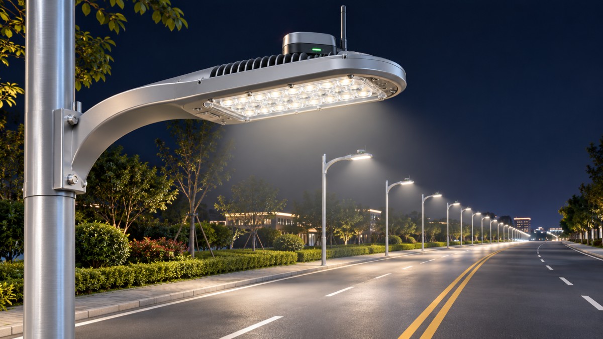
The driver determines what the controls can actually do
The LED driver converts the incoming supply to a controlled output for the LEDs. In a connected street light, it also determines which dimming commands can be accepted and how the luminaire responds. A driver described simply as “dimmable” is not enough: the control interface, wiring and supported functions need to match the intended controller.
A 0–10V interface can provide an analog dimming signal, but it does not by itself provide a digital network address, driver diagnostics or energy metering. Confirm the control characteristics expected by both devices, including the voltage-to-output relationship, minimum dim level and behavior when the signal is disconnected. A controller that requests zero output does not necessarily switch the luminaire off; that depends on the driver and any switching arrangement.
DALI is a digital lighting-control interface, but a DALI-capable driver is not automatically compatible with every outdoor management system. Confirm which DALI functions the driver and controller implement, whether the intended arrangement uses individual addressing, and what information can actually be read. A control node may translate between a management network and DALI at the luminaire; that translation needs to support the project’s required commands and fault reporting.
Other drivers support programmable stand-alone schedules without a communications network. That can be useful where fixed dimming periods are sufficient, but it is different from remotely changing schedules or receiving luminaire status. Specifications should distinguish between local time-based dimming, remote control and two-way monitoring.
Pay particular attention to behavior at low output. Verify the minimum stable dimming level, whether output changes smoothly, and whether the light is fully extinguished or remains at a minimum level. Where visible flicker, camera performance or sensitive applications matter, request relevant performance information at the intended dimming levels rather than assuming full-output data applies throughout the range.
A socket is an interface, not proof of interoperability
Outdoor luminaires may use a receptacle for a replaceable photocell or communications node. A NEMA-style receptacle or a Zhaga Book 18 interface can simplify installation and replacement, but the physical connection is only one part of compatibility. The pin configuration, available supply, control signals, mechanical fit and environmental sealing must match the chosen node.
For a NEMA-style connection, establish the actual contact configuration and which contacts carry power, switching or dimming signals. A node intended for one configuration cannot be assumed to provide the required functionality on another. For a Zhaga interface, confirm the socket location and the functions supported by the luminaire and node. A mechanically fitting controller is not necessarily able to dim, meter or report faults as specified.
The complete control path should be documented:
- Management platform: Issues schedules and commands and receives whatever status data the system supports.
- Communications network and controller: Carries commands to the luminaire and converts them into signals the driver can use.
- Driver: Interprets the local control signal and regulates LED output.
- Luminaire: Delivers the required light while operating within its electrical and thermal limits.
A failure or limitation at any link changes the result. For example, the platform may offer a midnight dimming schedule, but the luminaire will not follow it correctly if the node cannot communicate with the driver or has an incompatible dimming curve. Ask for a tested combination of driver, node and platform, including firmware versions and supported functions, rather than relying on separate compatibility claims.
Choose connectivity around coverage and operating behavior
A 200W street light does not require a particular wireless protocol. Cellular, radio-frequency mesh and other network architectures can all serve outdoor lighting, provided coverage, bandwidth and operating arrangements suit the site. Zigbee or another named protocol on a datasheet does not establish compatibility with a specific gateway or management platform; profiles, implementation details and integration support also matter.
Network choice should reflect the installation. A mesh arrangement depends on a viable communication path between nodes and gateways; pole spacing, terrain, street furniture and buildings affect that path. Cellular nodes depend on usable coverage and network service at each location. In either case, review commissioning arrangements, ongoing connectivity costs and the process for replacing a failed node without losing its identity or configuration.
The response to communications loss deserves an explicit requirement. A controller might retain its last command, follow a local schedule or revert to a preset level, depending on its design. Determine which behavior is acceptable for the road and confirm how the device recovers when communications return. A system that turns lights off during an outage may be unacceptable even if it performs well under normal network conditions.
Platform integration should also be demonstrated beyond a successful pairing. Test schedule changes, individual and group commands, alarm reporting, time synchronization and recovery after power interruption. If the project relies on a third-party platform, establish which data and control functions are exposed through its supported interface and who is responsible for resolving integration faults.
Separate measurement claims from control claims
Remote dimming can reduce energy consumption when lighting levels are lowered appropriately, but a controller’s reported dimming percentage is not necessarily the same as the percentage of electrical power consumed. Driver losses and the relationship between dimming command, LED output and input power affect the result.
For a simple comparison, a luminaire drawing a constant 200W for 4,000 hours would use 800 kWh per year. That is an arithmetic baseline, not a prediction of field use. A connected installation would require the actual operating schedule, measured or specified input power at each dimming level, and the consumption of the controller and associated equipment to estimate its energy use. Photocell switching hours and seasonal variation also affect the result.
If energy reporting supports billing, contractual performance or verification, specify whether the system uses measured input energy or an estimate derived from operating hours and dimming levels. Request the meter’s accuracy, measurement range and installation arrangement, and check the requirements applicable to the intended use. A platform display with kilowatt-hours is not, on its own, evidence of revenue-grade measurement.
Check the electrical and environmental limits of the complete assembly
The control node and socket are exposed to the same outdoor environment as the luminaire. Adding a node can change the installed assembly’s height, wind exposure or sealing arrangement. Confirm the ingress protection and mechanical suitability of the assembled configuration, including any receptacle cap, gasket or connector that will be used in service.
Surge protection is particularly important on outdoor lighting circuits exposed to switching events and lightning-induced transients. Check the luminaire’s declared surge withstand and protective device arrangement against the project specification and local conditions. The protective device’s ratings, connection scheme and end-of-life behavior matter; a headline surge value without those details is difficult to assess. The node and communications interfaces must also be considered, not just the LED driver.
Confirm supply voltage range, frequency, earthing arrangement and the effect of the driver’s inrush current on circuit protection and switching equipment. Inrush is relevant when multiple luminaires switch on together: a circuit can be within its steady-state load rating and still experience nuisance tripping. The 200W nominal rating is not sufficient to size that behavior.
Thermal performance should be assessed at the specified ambient temperature and mounting conditions. LED output, driver life and control electronics can be affected by heat. Compare declared lifetime and lumen-maintenance claims on a consistent basis, including operating temperature, drive current and failure criteria. A lifetime figure alone does not establish the expected service life of every component in the assembled smart luminaire.
Electrical safety, electromagnetic compatibility and photobiological or road-lighting requirements depend on the destination and application. Ask for documentation applicable to the complete product and intended market, including any changes introduced by the control node. A component certificate should not be treated as automatic evidence that the final assembly meets every project requirement.
What should be demonstrated before approval?
A sound evaluation connects the paper specification to the intended installation. Request the exact luminaire, optic, driver, socket and controller configuration; a photometric calculation; electrical and environmental ratings; and a functional description of the network and platform. Where interoperability is central to the project, a representative bench or pilot test should exercise the actual devices and software versions proposed for deployment.
The acceptance test can be focused on consequential behaviors: switching and dimming across the required range; schedule execution; individual and group control; reported faults and energy data; power-cycle recovery; and operation during a simulated network loss. Compare measured input power with the data used in the energy calculation. Record any features that depend on a gateway, subscription or proprietary integration, so that ongoing operation is not assumed to be part of the luminaire itself.
A 200W smart street light is an appropriate selection when its optics meet the road design without unnecessary overlighting, its driver and node support the required control functions, and the assembled system behaves predictably under normal and failed conditions. If any of those conditions is unresolved, the wattage and the presence of a “smart-ready” socket are not sufficient grounds for approval.
Recommended News