
Search News
Industry Portal
Hot Articles
How to size pilot holes for thread-rolling fasteners in aluminum
Time
Click Count
Start with the pilot-hole diameter specified for the exact thread-rolling fastener and aluminum application, then validate a controlled range around that starting point. The usable hole size must provide enough aluminum for the screw to form load-bearing threads while keeping installation torque, fastener stress, and joint distortion within acceptable limits. A diameter taken from a conventional tapping chart or calculated from the screw’s nominal outside diameter alone does not establish that balance.
For thread rolling fasteners for aluminum, the hole is part of the forming process. As the screw enters, its forming features displace material into the spaces between threads. Hole diameter, alloy condition, available engagement length, and the shape of the entry all affect the resulting joint. The correct production specification is therefore a diameter range supported by installation and joint testing, not simply a drill size that produces a promising first assembly.
Choose a starting diameter from the fastener specification
Identify the screw by its complete geometry and size before selecting a hole. Two fasteners with the same nominal thread diameter can require different pilots because their thread pitch, forming lobes, lead shape, and crest dimensions differ. Use the fastener supplier’s hole recommendations for aluminum, including any distinctions for material thickness or alloy condition. If the available table covers steel or plastic but does not address aluminum, request relevant data rather than transferring the value directly.
Confirm what the published dimension describes. A recommendation may refer to a drilled hole, a punched hole, a cast opening, or the finished diameter after a secondary operation. A table may also give a nominal drill size while the drawing needs a finished hole tolerance. The dimensions are related, but drill size alone does not control the actual opening: tool wear, machine condition, and hole-making method affect the result.
Before testing, record the joint configuration alongside the proposed pilot:
- The exact fastener designation, length, coating, and forming geometry.
- Aluminum alloy and temper, or the applicable casting specification and condition.
- Effective thickness available for thread engagement, including any boss, recess, or exit feature.
- Hole-making method, intended diameter limits, entry treatment, and any lubricant.
- Required clamp load or tightening torque, service loads, and any pull-out or reassembly requirements.
These details make a published starting size meaningful. A value validated in a thick machined boss cannot automatically be applied to a thin punched flange, even when both use the same screw.
Account for the aluminum and the available engagement
Aluminum is not one uniform forming material. Alloy composition, temper, hardness, and casting condition influence the force needed to displace material and the way the formed threads carry load. A pilot that installs smoothly in a more ductile condition can demand excessive torque or produce local cracking in a harder or less accommodating condition. Cast material also warrants attention to porosity and surface condition, particularly where a narrow boss leaves little material around the hole.
Engagement length changes the result as well. In a thicker member, more threads participate in forming, which can increase driving torque and resistance to stripping. In a thin sheet, fewer threads carry the load, and entry deformation consumes a greater share of the available thickness. Enlarging a difficult hole may reduce torque, but it also reduces the material available to form the internal thread. If the joint cannot meet both installation and strength requirements within the permitted hole range, consider a different fastener geometry, more engagement, or a different joint design.
Measure effective engagement rather than assuming that it equals the screw’s full threaded length. The lead threads may not produce complete engagement at the entry, and a screw entering a blind hole needs clearance at the bottom. A counterbore, chamfer, or non-threaded portion of the joint can further reduce the length that carries load.
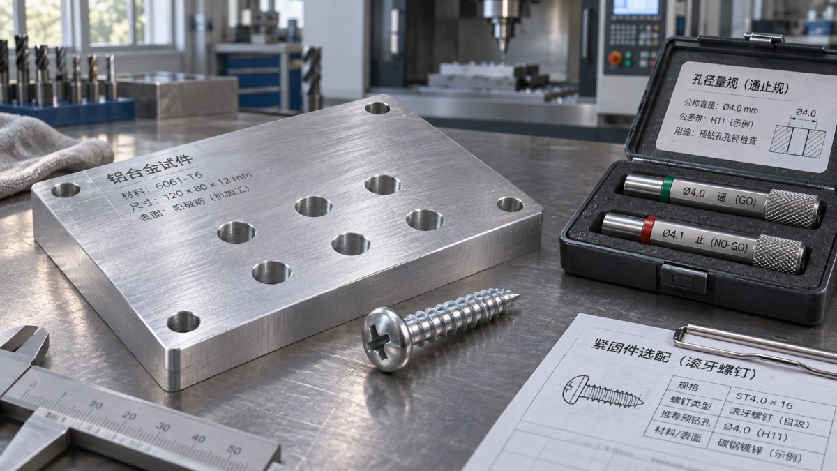
Control the hole that the fastener actually enters
A drilled, punched, and cast hole can share the same measured diameter yet behave differently during installation. Drilling may leave burrs or an irregular entrance. Punching can produce a tapered opening, fracture zone, and directional burr. Cast openings can vary in roundness and include draft. These features affect how the screw starts and how much material it encounters along its path.
Measure the opening at relevant locations, especially when the hole is tapered or out of round. For a punched part, identify the intended screw-entry side and keep it consistent during testing. Record whether the reported diameter is taken at the entry, exit, or another specified location. A single measurement at the easiest point can conceal a tighter section that governs forming torque.
Entry geometry also needs control. A small chamfer can aid alignment and starting, but an excessive chamfer removes material from the first engaged threads. Burrs can interfere with seating or distort the first portion of the torque trace. Specify a treatment that can be reproduced by the production process, then include that treatment in the validation samples.
Blind holes need a separate depth allowance
For a blind hole, distinguish pilot diameter from pilot depth. The screw must form the required engagement without its tip or unformed lead contacting the bottom. Account for the actual drill-point shape, depth tolerance, screw length tolerance, and any coating or debris that occupies the bottom of the hole. A sudden torque rise near the end of insertion can indicate bottoming rather than an undersized pilot.
If a screw bottoms before the head clamps the joint, increasing tightening torque will not correct the condition. Confirm the remaining depth and screw penetration first. Where the design permits, adjust usable hole depth or screw length and repeat the installation test.
Establish a workable diameter range through testing
Prepare representative parts at several finished hole diameters around the manufacturer’s starting value, including the proposed upper and lower production limits. The increments should be small enough to reveal the transition between excessive forming torque and inadequate thread performance. Measure the actual holes and group results by measured diameter, not only by the drill or punch designation.
Use the intended fastener, coating, installation speed, alignment, and lubrication condition. Include representative variation in aluminum and hole production where those variables are expected to change. Start with fresh holes for each installation; a previously formed hole has a different internal profile and cannot represent first assembly.
Capture the torque curve from initial engagement through seating and final tightening. The trace separates the torque needed to form threads from the torque applied after the head contacts the joint. A single peak value can obscure where the resistance occurred. Record visible damage, starting behavior, seating condition, and any fastener breakage alongside the torque data.
Then test the assembled joint against its requirements. Depending on the design, this can include clamp-load verification, axial pull-out, internal thread stripping, and tests under the relevant service loading. Pull-out performance alone does not establish that the joint has sufficient clamp load or resistance to loosening. Define acceptance limits before comparing diameters so the selected range reflects the intended function.
The result should leave a usable tightening window between the torque needed to form and seat the screw and the torque at which the fastener or internal thread fails. Set the production tool target and limits within that window, accounting for tool variation and the full specified hole range. A pilot that works only with a carefully controlled laboratory tool at one diameter is a weak basis for a production tolerance.
Read installation symptoms in context
Do not diagnose the pilot from torque alone. A dry fastener and a lubricated fastener can show different torque for the same hole, while a worn driver or poor alignment can change the apparent installation behavior. Hold those conditions constant when comparing hole diameters, and investigate changes before revising the drawing.
Turn the test result into a production specification
Specify the finished hole diameter and tolerance that passed validation, along with the measurement location if taper or entry variation matters. State the hole-making method and entry-side requirements where they affect performance. For blind holes, include the usable depth requirement separately from the diameter. Identify the aluminum condition and the fastener designation used to establish the limits.
Installation controls belong with the joint specification too: tightening method, tool limits, lubrication or dry condition, and any restrictions on reuse. A thread-forming screw may follow an existing thread on reinstallation rather than form a new one; whether that joint retains adequate performance requires separate testing.
Revalidate when a change alters the forming conditions. A different alloy temper, punch direction, screw coating, or boss thickness can shift the relationship between diameter, torque, and strength even if the nominal screw size remains unchanged. Retaining measured hole data and torque curves makes that comparison much easier than relying on the original drill callout alone.
Recommended News