
Search News
Industry Portal
Hot Articles
How torque control prevents joint failure in industrial fastening systems
Time
Click Count
A bolted joint rarely fails because a wrench “did not turn far enough.” It fails because the installed preload was too low, too high, or too inconsistent to keep the clamped parts working as one assembly. Industrial fastening systems torque control is therefore not simply a method for applying a specified rotational force. It is a controlled way to create repeatable clamp force, limit variation between assemblies, and protect the joint from loosening, fatigue, leakage, distortion, or bolt fracture.
For technical evaluation, the central question is not “What torque can the tool deliver?” It is: Can the complete fastening process create and verify the required clamp load under real production conditions? The answer depends on the fastener, joint materials, lubrication state, seating behavior, tool capability, and the method used to confirm the final result.
Torque creates clamp force, but it does not measure it directly
When a bolt is tightened, the applied torque is consumed in several places. A relatively small portion stretches the bolt and produces useful clamp force. Much of the input is lost to friction under the bolt head or nut face and within the threads. This is why the same torque setting can generate meaningfully different preload when the surface condition changes.
A dry zinc-coated fastener, a lubricated fastener, a stainless steel assembly, and a bolt installed through a painted flange may all respond differently to the same nominal torque. If the torque target was established for one friction condition and applied to another, the joint can be under-tightened or overloaded even when the operator follows the work instruction exactly.
Torque remains widely used because it is practical, fast, and compatible with handheld, pneumatic, electric, and automated tools. Its limitation is that torque is an indirect indicator of bolt tension. A sound fastening specification treats torque as part of a controlled system rather than assuming that one torque number guarantees one clamp load.
Why insufficient clamp force leads to joint failure
A correctly preloaded bolted joint holds the connected components together tightly enough that external loads are transferred primarily through the clamped interface. Under vibration or fluctuating service loads, that preload helps prevent separation and relative movement between the parts.
When preload is too low, the joint can begin to slip. Small movements may wear coatings, polish contact surfaces, enlarge holes, damage threads, or reduce the remaining preload. Vibration can then rotate the nut or bolt loose. In a sealing joint, insufficient compression can cause leakage long before the fastener visibly backs out. In structural or rotating equipment, repeated movement increases the bolt’s cyclic stress and raises fatigue risk.
The important point is that a bolt does not need to fall out for the joint to have failed. Loss of clamping, loss of alignment, gasket leakage, fretting corrosion, and progressive fatigue damage are all forms of joint failure that torque control is intended to prevent.
Over-tightening is a different failure path
More torque is not a universal safety margin. Excessive torque can stretch a bolt beyond its intended elastic range, damage threads, crush softer joint members, distort a flange, or overload a gasket. A fastener that has yielded may initially appear secure, but its clamp load can become unstable in service.
Soft materials make this problem more pronounced. Aluminum housings, composite panels, coated sheet metal, plastic components, and gasketed assemblies may be damaged before the bolt itself shows an obvious problem. In these joints, a high-capacity tool with a broad torque range is not necessarily the right choice. Control resolution, shutoff accuracy, reaction management, and seating detection can matter more than maximum output.
Thread stripping is another concern, particularly where a steel bolt engages directly into a softer tapped material. The allowable torque is then constrained by the female thread, not only by the bolt grade. A torque target copied from a through-bolt-and-nut application may be unsafe when used in a tapped casting or thin-walled component.
The joint, not the tool, should determine the fastening strategy
A torque-controlled tool can only perform well when the joint design and assembly condition are understood. Before selecting a tool or programming a fastening cycle, evaluate the variables that determine whether torque is a reliable proxy for clamp force.
- Fastener geometry and strength: Diameter, pitch, grip length, head style, material, and strength class influence the torque-tension relationship and the acceptable preload range.
- Joint stiffness: A short, stiff joint and a long, compliant joint react differently to load and relaxation. Bolt stiffness relative to clamped-part stiffness affects how external load changes bolt tension.
- Surface condition: Coatings, plating, paint, corrosion, burrs, lubrication, washers, and thread-forming operations change friction and seating behavior.
- Joint type: A structural flange, pressure seal, electrical busbar, machine guard, wheel assembly, and gearbox cover do not have the same failure modes or verification needs.
- Service environment: Vibration, temperature cycling, moisture, chemical exposure, and load reversals can reduce preload or accelerate fatigue after installation.
- Access and ergonomics: Poor socket engagement, unstable operator posture, restricted reaction-arm placement, or angled tool access can introduce inconsistent installation results.
A torque value should be validated for the actual combination of bolt, nut or threaded hole, washer, coating, lubricant, and joint materials. Treating torque as a permanent property of the bolt alone is a common specification error.
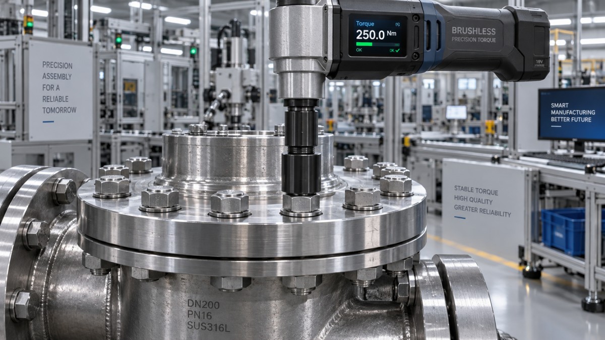
How controlled tightening reduces variation on the line
Manual fastening is often judged by operator technique: use the specified wrench, set the torque, and tighten. That approach can be adequate for low-risk maintenance work, but it is weak where joint integrity must be consistent across many units. A controlled fastening process reduces variation at several stages.
First, the tool must reach the target without excessive overshoot. A mechanical click wrench, clutch tool, pulse tool, transducerized electric tool, and hydraulic tensioning method all control tightening differently. Their suitability depends on the joint and the required confidence level, not on a simple ranking of tool types.
Second, the fastening cycle should distinguish between rundown and final tightening. During rundown, the fastener turns freely until the joint seats. Final tightening begins after contact is established and resistance rises. A tool that applies high output before seating can damage threads, cross-thread components, or introduce unnecessary impacts into the assembly.
Third, the process should detect abnormal signatures. A joint that reaches torque too early may have cross-threading, debris, damaged threads, or excessive friction. A joint that turns too far before reaching torque may have a missing washer, a soft component, an incorrect fastener, stripped threads, or incomplete seating. Torque alone is useful; torque combined with angle, time, and cycle monitoring provides more diagnostic value.
Torque-angle control is useful when friction variation cannot be ignored
Torque-angle tightening adds a rotation requirement after a defined seating point or initial torque threshold. It does not eliminate friction effects, but it can improve control by checking whether the fastener rotates through the expected range while clamp load is being developed.
This approach is particularly useful when an assembly needs stronger confirmation than final torque alone can provide. For example, if a bolt reaches the torque target with unusually little rotation, friction may be consuming too much of the applied torque. If it requires excessive rotation, the joint may be settling, deforming, or missing a component. The acceptable angle window can expose these conditions.
Torque-angle control is not automatically appropriate for every joint. It depends on a stable, well-defined seating condition. In joints with highly variable soft materials, compressible seals, irregular painted surfaces, or changing stack thickness, a simple angle window may generate false rejects or fail to represent actual clamp load. The tightening method should reflect the physics of the joint rather than the capabilities of a preferred controller.
Relaxation and embedment can erase an apparently correct installation
A joint may meet its installation torque target and still lose preload soon afterward. This commonly happens through embedment: microscopic high points on contact surfaces flatten under load. Coatings, washers, paint layers, soft materials, gasket compression, and imperfectly seated interfaces can all contribute.
Thermal cycling is another source of preload change. If the bolt and clamped members expand at different rates, temperature changes can alter bolt tension. A joint that is stable at room temperature may see reduced clamp force or elevated bolt stress during operation. This does not mean torque control is ineffective; it means the specified preload and fastening method must account for the service condition.
Where relaxation is expected, process design may include controlled re-torque, a staged tightening sequence, hardened washers, improved bearing surfaces, an alternative fastener design, or a clamp-load verification method. Re-torque should not be treated as a routine cure for an undefined problem. Turning a settled fastener again can change friction and introduce a new preload condition unless the procedure is engineered for that purpose.
Sequence control matters on multi-bolt joints
On covers, flanges, structural connections, and gasketed assemblies, tightening one fastener affects the load carried by the others. A random sequence can distort the joint, create uneven gasket compression, or cause early-tightened bolts to lose preload as neighboring bolts are installed.
A staged cross-pattern sequence helps bring the assembly together progressively. The purpose is not merely to follow a familiar pattern; it is to distribute seating and compression so that the final joint is more uniform. The required sequence depends on component geometry, bolt count, stiffness, and sealing requirements. Complex joints may require a documented tightening plan rather than a generic star pattern.
For automated lines, sequence control should be embedded in the controller so that the system verifies the correct location, tool program, and completion status. This is especially valuable where several fastener sizes or torque targets are used on the same product.
Verification should match the consequence of failure
Tool calibration is necessary, but calibration alone does not prove that the installed joint has the intended clamp force. It confirms that the tool behaves within its defined operating condition. The assembly process also needs periodic validation against the joint.
For lower-risk applications, documented tool calibration, operator training, correct sockets, and sample audits may be sufficient. Higher-risk assemblies may justify rundown monitoring, torque-angle signatures, residual torque checks, prevailing-torque evaluation, direct bolt elongation measurement, ultrasonic verification, or other tension-focused methods. The correct method depends on whether the main concern is loosening, leakage, fatigue, structural separation, or damage to the clamped material.
Residual torque deserves careful interpretation. It is not the same as original installation torque or actual clamp load because breakaway behavior is affected by static friction. It can be a useful audit indicator when the method is consistently defined, but it should not be treated as a direct preload measurement.
What to specify before approving a fastening system
A practical evaluation starts with the joint and works outward to the tool, controller, and quality records. The approval package should define the fastener and mating components, target torque or tightening strategy, permitted surface condition, lubrication policy, socket and extension configuration, sequence, acceptance limits, calibration interval, and response to failed cycles.
It should also identify changes that require revalidation. Switching a coating supplier, adding lubricant, changing a washer, revising a paint process, replacing a pneumatic tool with a brushless DC tool, or altering the bolt source can all change the installed clamp force. These are process changes, not minor purchasing substitutions.
Industrial brushless tools can offer compact power, programmable shutoff, and integration with traceability systems. Those advantages are valuable when the joint study, tool program, and assembly conditions are aligned. They cannot compensate for an undefined torque target or uncontrolled friction.
The most defensible fastening decision is therefore not the one with the highest torque capacity or the most data fields. It is the one that demonstrates repeatable preload for the real joint, detects abnormal assembly behavior, and provides verification proportionate to the consequence of failure.
- Last One:No more articles
- Next Article:What drives smart access systems price for a multi-site rollout?Sep 28, 2026
Recommended News